|
|
|
 |
|||||
 |
|||||
 |
|||||
This project is about implementation of a two
digit totalising counter. This
counter has got practical applications in many fields like audio oscilloscope,
Multimeter, digital watches etc.
It is also used in banks but the count is randomly generated. The
basic idea in which the project is based is the conversion of BCD
counter to a seven segment decoder circuit.
The
circuit basically consists of Mod–10
counters (IC-7490) and seven –
segment display LED (FND) and also BCD
to seven segment decoder (IC-7448).
IC-7448
is a BCD to seven segment decoder and is useful as a driver circuit to a common
cathode FND. The BCD code is a 4 bit code which counts from 0 to 9 and the
counts from 10 to 15 are considered to be don’t cares. This BCD count will be
generated by a mod-10 counter which is discussed later.
The
IC-7448 converts the BCD count into a seven segment count. The fashion of seven
segment counting as the BCD inputs proceeds from 0 to 9 has been illustrated in
the truth table. The seven segments are
named a, b, c, d, e, f & g.
These segments of FND 500/560 wherein the cathode of the LED’s of the FND have
been grounded. Here since we require a two digit totalising counter which
counts from 0 to 99 we require two IC-7448 and two FND’s.
The truth
table is as follows:-
|
D
|
C |
B |
A |
a |
b |
C |
D |
e |
f |
g |
|
0 |
0 |
0 |
0 |
1 |
1 |
1 |
1 |
1 |
1 |
0 |
|
0 |
0 |
0 |
1 |
0 |
1 |
1 |
0 |
0 |
0 |
0 |
|
0 |
0 |
1 |
0 |
1 |
1 |
0 |
1 |
1 |
0 |
1 |
|
0 |
0 |
1 |
1 |
1 |
1 |
1 |
1 |
0 |
0 |
1 |
|
0 |
1 |
0 |
0 |
0 |
1 |
1 |
0 |
0 |
1 |
1 |
|
0 |
1 |
0 |
1 |
1 |
0 |
1 |
1 |
0 |
1 |
1 |
|
0 |
1 |
1 |
0 |
0 |
0 |
1 |
1 |
1 |
1 |
1 |
|
0 |
1 |
1 |
1 |
1 |
1 |
1 |
0 |
0 |
0 |
0 |
|
1 |
0 |
0 |
0 |
1 |
1 |
1 |
1 |
1 |
1 |
1 |
|
1 |
0 |
0 |
1 |
1 |
1 |
1 |
0 |
0 |
1 |
1 |
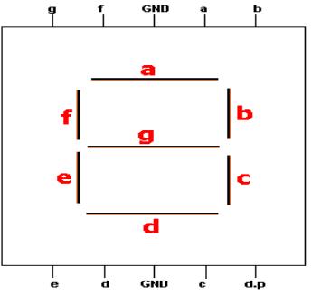
BASE
DIAGRAM OF FND(LT-543)
decade Counter:-
The
entire idea behind the totalising counter is that it counts from 0 to 99 and
then resets to 0 and starts counting again in this repeated manner. Thus the
basic logic lies behind the design of the counter which generates the count of
the digit in the units place in the usual manner that is for every clock pulse
it gives an increment in the count and thus counts from 0 to 9 but the count in
the ten’s place should be incremented by 1 only at
the eleventh pulse. Thus we
require two modulo – 10 counter for
the purpose such that the units place counter counts from 0 to 9 in usual
manner and the tenth place counter changes to count after every 10th
clock pulse.
As
the circuit demands we need two mod – 10 counter. The Ro1, Ro2,
Rg1, Rg2 of the units place counter is shorted with that
of the 10th place counter and initializing of any one can be done.
The output from both the counter are given to the respective inputs of IC’s
7448. On initializing the FND’s display 00.
The truth table for initializing the mod – 10 counter is as
follows:-
|
Ro(1) |
Ro(2) |
Rg(1) |
Rg(2) |
Qd |
Qc |
Qb |
Qa |
|
High |
High |
Low |
X |
Low |
Low |
Low |
Low |
|
High |
High |
X |
Low |
Low |
Low |
Low |
Low |
|
X |
X |
High |
High |
High |
Low |
Low |
High |
|
X |
Low |
X |
Low |
Count |
Count |
Count |
Count |
The
key factor of the circuit is that the Q3 output of units place
counter is given to the clock input of the counter of the tenth place. The mod – 10 counter is basically negatively
leveled triggered master salve J-K flip flop. Here when the clock input to
the second counter changes form 1 to 0 it counts. Q3 that is MSB
of the units place counter
changes from 1 to 0 only at the eleventh pulse due to the 10th place
counter which when receives a
clock pulse and it counts. The
count continues. At 99 the counter again resets to 00 & due to the basic
logic of the mod – 10 counter.
The truth
table for mod-10 counter is as follows:-
|
Count |
Qd |
Qc |
Qb |
Qa |
|
0 |
off |
off |
Off |
Off |
|
1 |
off |
off |
Off |
On |
|
2 |
off |
off |
On |
Off |
|
3 |
off |
off |
On |
on |
|
4 |
off |
on |
Off |
off |
|
5 |
off |
on |
Off |
on |
|
6 |
off |
on |
On |
off |
|
7 |
off |
on |
On |
on |
|
8 |
on |
off |
Off |
off |
|
9 |
on |
off |
Off |
on |
WORKING
:-
There
are 2 switches used in the circuit, viz. the reset switch and the alarm switch. Until the reset switch is not
pressed there is no effect of clock pulse on the circuit. Once the reset switch
is ON the circuit is ready. Now we start giving the clock pulse. With each
clock pulse the LSB counter is incremented by 1.
When
the LSB counter reaches 9 the next clock pulse makes the LSB 0 and the MSB
counter is incremented by 1. For this Q4 of LSB is given to the
clock of MSB. This continues until 98 is reached.
The next clock pulse makes count 99 and the beeper starts
beeping. For this Q1 and Q4 of LSB and MSB are ‘anded’
and the output is given to the input of the beeper. Other input of the beeper
is grounded. This beeper keeps on beeping.
To stop the beeper
another switch is provided. This switch works only when the beeper is ON and on
pressing this switch the beeper stops working.
When
we stop the beeper it does not mean that the circuit is reset. Only the beeper
is stopped. When the beeper switch is
again ON, the counter is still on 99. Now when the reset switch is
pressed then the beeper stops
beeping and the circuit is reset to 00.
CONCLUSION:-
The “TWO DIGIT
TOTALISING COUNTER” counted from 00 to 99 with increment of 1 per clock
pulse. As soon as 99 was reached the
beeper started beeping. At this state there was no effect of clock pulse on the
counter. When the reset switch was
pressed, the counter was reset to 00 and the beeper stopped beeping.
Thus
the circuit worked perfectly as required.